Rig Atelier
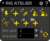
In this window are all the tools for building and modifying your skeleton/IK/Reverse Foot.
We completely rebuilt the joint node to have the ability to use it directly, without any rigging layer upon. So, when a joint is skinned to a mesh you can select it directly: click on the corresponding mesh area and it will select the joint automatically.
Bind Pose (or Build Pose) mode only
All the Rig Atelier commands must be performed into "Bind Pose" or "Build Pose" mode of the Character Bank (). It means, that these commands are disabled in "Skin & Check" mode or "Ref Pose".
Same rules applies if you want to use/keep using the Auto Rig window(since it belongs to the Rig Atelier)
Auto Rig : Select your 3D models) and quickly generate a biped rig. Clicking on this button will open up our Auto Rig Window
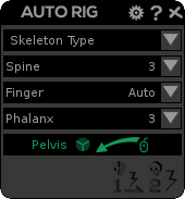
Auto Rig Window
Once opened, you will need first to place hotpoints on corresponding zones of your character
Choose the side first
When placing hotpoints, you'll need to decide which side of the character you want to rig, so you'll only need to place hotpoints on the left or on the right side. Do NOT mix both sides when placing hotpoints, it will lead to unexpected results
To do so, simply click Left on the first field
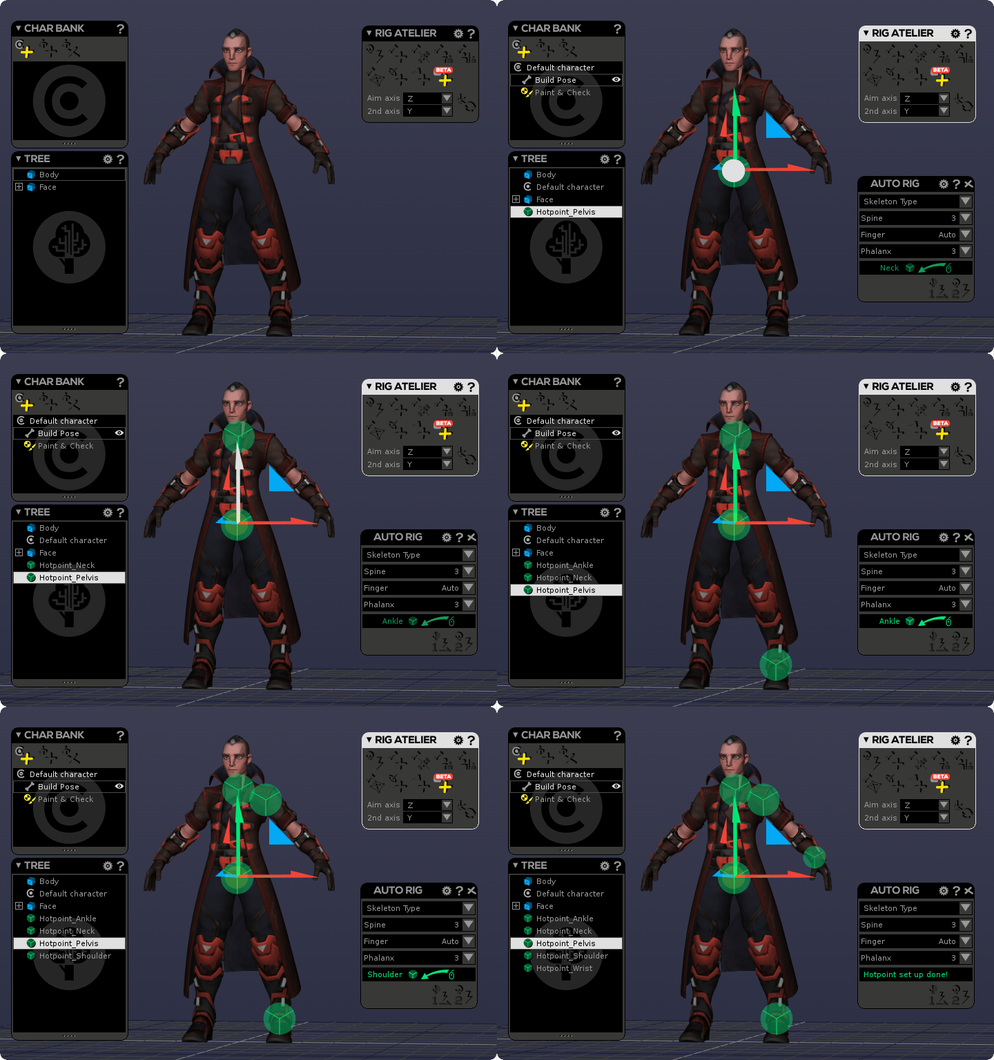
and hold & drag your mouse over your character to place your first Hotpoint (which is the pelvis)
This will generate a big green wheel :
Then, do the same for the Neck
Then goes the Shoulder
And the Wrist
To finally end with the Ankle
Once finished, you'll see a note which tells you all hotpoints have been set
Here is a quick how-to proceed gif :
Adjustments
At this step, you can adjust your hotpoints if the automatic positioning of Akeytsu placed them a bit off of the desired position. While you can rotate them in order to ease their positioning, keep in mind that rotate does not affect the final skeleton
Then, you have 3 fields to check :
- Skeleton Type : There you can choose whether you want a Unreal Engine 4, Unity, or a custom naming convention for your skeleton. Choosing a skeleton will activate both generation buttons on the bottom-right corner of the Auto Rig window. Custom skeleton can be edited in the Autorigger preferences
- Spine : offers you a quick and easy way to define how many joints you want from the pelvis to the neck (excluded). So for example if you set 2 spine joints, the hierarchy will be : Pelvis>Spine_01>Spine_02>Neck
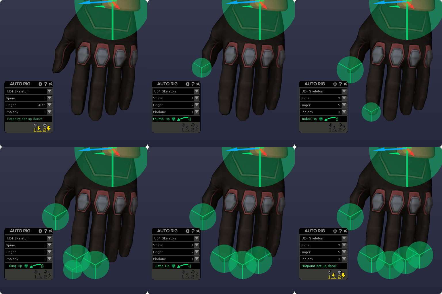
- Finger : Let you decide if you want to auto-detect fingers or if you want to place manually hotpoints for fingertips, as show below :
- Phalanx : Allows you to decide how many finger phalanxes you need for your character's hands
Once you're done with these settings, you will use a "Two-Steps process" to generate the final skeleton, controls and skinning :
Auto Rig1st Step: The 1st command will generate a half-skeleton as well as skinning base. You will then need to eventualy adjust the position of joints to match your character morphology (in bind pose mode) and refine the skinning using paint tools (in paint & check mode).
(In the current version) About skinning, please do not manually tweak your smooth weights () but tweak your rigid weights () instead because the Auto Rig 2nd Step will process smooth weights from your rigid weights and not "mirror only" your current smooth weights! It means that potential smooth manual tweaks would be lost at the end of the process.
It gives you control, but takes also some time to place, auto-orient, and adjust orients so the skeleton meets your needs at best. Don't forget to toggle on the sticky aim if you want to preserve orients.
Auto Rig 2nd Step: The 2nd command will generate many things: the other half part of the skeleton, full smooth skinning from 1st half rigid weights, then both IKs and Reverse Foots. So you end up with a character ready to be animated!
You can also directly use this button and bypass the first step if you want to have your rig done in one click, but please understand that you will lose control over the final result since you won't be able to edit where the skeleton joints are placed (this, as well as the skinning, can be edited later)
Joint Features
Create Joint (Shortcut: J): Add a new joint. To do so, press this button and LMB click anywhere on the 3D viewport. Until you press Enter (or unactivate the feature), it will create a new joint each time you LMB click on the 3D Viewport. During creation process you can move a joint untill you release the (creation) click.
Mesh detection
Joint display
Navigating in the 3D viewport while creating joints
Insert Joint: To activate it, this button requires to have a hierarchy of at least two connected joints. Press this button and click LMB somewhere along a bone to insert the new joint. Until you release the (creation) click you can move along the hosting bone axis to place your new joint at the desired place.
Parent Joint: Parent two joint by selecting first the joint to parent and then its father. By the way, if you select four joints and click on the command, the three joints you selected first will be parented under the fourth selected joint.
Unparent Joint: Unparent selected joints.
Center Joint: Center the current joint's position right in the middle of a vertex selection
IK
Bind Pose (or Build Pose) mode unsafe-only
IK or Reverse Foot must be created into the "Bind Pose" or "Build Pose" mode of the Character Bank (). It means, that these IK commands are disabled in "Skin & Check mode" or "Ref Pose".
What is IK in common pipelines... and why Akeytsu is so different?
In 3D animation you may animate a skeleton in two ways: forward kinematic and inverse kinematic. Both have their benefits and inconveniences but they need to be used in a complementary way.
Forward kinematic (called FK) is a posing technique where each joint is moved, its child bone inheriting its location and rotation. It means that you have to transform your joints, one by one, from parents to childs. For instance: if you want to achieve an arm posing, you have to first position the shoulder, then the arm up to the hand. When there are many joints, this may be fastidious. However, this technique allows to precisely build the posing you want as you interact with each joint.
Inverse kinematic (called IK) works the opposite way : you manipulate a target snapped to the last joint of a chain (leaf) and parent joints in that chain are automatically transformed so that the leaf follows the target. In our previous example, achieving an arm posing with IK would only require to position the hand and the other joints up to shoulder would follow. The other main benefit about IK is the ability to lock the target's World coordinates during interpolations.
Usually IK/FK workflows requires two separated skeletons: one for IK and one for FK. Meaning you have to keyframe both skeletons and manually blend between them according to the result you seek. It is considered as quite a complicated process...
... but things are very different in Akeytsu!
Instead of having two skeletons, we just have one "FK" skeleton. It can be considered as the "default "skeleton and IK may be used directly on it.
Create IK (Shortcut: Y): Add an IK solver to your joint chain.
To do so, select the father joint and then the leaf joint (last child) of that chain. The IK target will automatically appear around the leaf joint pivot (you do not need to create a curve controller).
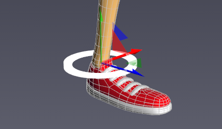
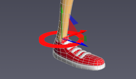
This target allows two different behaviors : FK or IK. You switch from IK to FK just by RMB clicking on the target.
Layer and String Joints
The IK (and Reverse Foot) controller cannot be used independently from the joints it handles. So an animation layer containing a controller cannot spare the string joints. This is why adding a controller in a layer (enabling the hammer icon in the picker dialog) will automatically add the string joints. Conversely, deleting a string joint from the layer also deletes the controller.
FK Behavior:
When the target is white, the FK behavior is on. It means you may transform your joints in FK as well as move your character and your targets will follow. However, you may still manipulate the target to affect the whole chain's posing.
During an animation, the IK string interpolation between two keys showing at least one white target, simply shows the string joints interpolation, as it would be if there was no IK target.
IK Behavior:
When the target is red, the IK behavior is on. You may only manipulate the target and if you move your character your targets will remain locked.
During an animation, the IK string interpolation between two keys, both showing red targets, solves the string on each frame with the interpolated IK transform values (position, orientation, pole angle).
Recommended workflow
What consequences about deleting IK targets?
IKs and animation layers
As a rule, IK visual feedback is only guaranteed to be correct when a layer is displayed on its own (e.g. at full opacity and all other layers at 0 opacity or hidden).
Spinner & IK
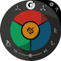
When an IK target is selected, the Spinner rotate part displays a new circular area to control the rotation around the IK Pole Vector (or Pole Angle), the root to leaf vector.
Standard MRS areas, though smaller, work in the same fashion as usual and modify the leaf's rotation.
Its value is exposed in the Transform window, and the Curveboard shows an orange curve representing it.
Two different ways to use the Pole Vector
Spinning the Pole Vector using RMB does rotate the leaf joint too while spinning it using LMB does not!
Reverse Foot
What is it? How it works?
The Reverse Foot is a controller allowing you to work on a human leg and foot with simplicity. Usually, in standard pipelines setting up a Reverse Foot is a complicated technical step but in Akeytsu, you do it like a breeze, in two clicks ! You have to select Father and Leaf joints separated by at least 2 other joints, or more, and click on the Create Reverse Foot button
Once created, it mainly does 3 things:
- You can move the controller, the foot will follow, and the rest of the leg will place and orient consistently (see the IK controller). According to the mode you chose the resolution to be (IK or FK), moving the hierarchical ancestors of the leg (eg. the root joint) will act differently
- The Spinner displays 3 new angles, called “roll”, “twist” and “bank”, allowing you to bend the foot with an usual and coherent limb movement around the 3 world axes in a simple way. Their value is accessible in the transform window, and the curveboard shows orange curves representing them.
- Similar to standard IK target, the Reverse Foot controller shows a particular rotation mode, that rotates the leg around the hip-ankle axis, called Pole Vector (or Pole Angle) rotation.
Create Reverse Foot: Add an automatic reverse foot to your joint chain.
To create a reverse foot, just select Father (usually thigh) and Leaf (usually ball) joints and hit the command. It automatically sets up a sole/target and 4 locators, positioned by default at their estimated place on the front, back, right and left of the foot skinned mesh. You may need to adjust them by positioning and orienting them so that the roll, twist and bank anchors and rotation directions are perfect.
Exactly like the (standard) IK, the Reverse Foot allows two different behaviors : FK or IK. You switch from IK to FK just by RMB clicking on the sole/target.
FK Behavior:
When the sole is white, the FK behavior is on. In this case, moving the hierarchical ancestors of the leg (eg. the root joint) will cause the controller (and consequently the foot) to move alongside, leaving the leg joints relative positions unchanged. By the way you can handle your thigh, knee and ankle joints directly in FK. Useful behavior to move a piece of skeleton and take the controller with it.
IK Behavior:
When the sole is red, the IK behavior is on. In this case, moving the hierarchical ancestors of the leg (eg. the root joint) will forbid motion on the controller, anchoring its position in the 3D world, and consistently placing and orienting the leg and foot. Useful behavior to handle contacts on the ground or on a precise point of the 3D world.
During an animation, the reverse foot follows the same rules as the IK controller between two keys showing a red target, hence roll, twist and bank angles are also interpolated to solve the joints positions on each frame.
Recommended workflow
Reverse Foot creation requirements
The Reverse Foot creation consists at least in a set of 4 joints (thigh → knee → ankle → ball) that are not already constrained by an IK controller or another Reverse Foot controller. Since Akeytsu 2019-2-1 Reverse Foot leg has an arbitrary length
No FK handling on ball joint and no scaling allowed
- The ball joint is the only joint of the Reverse Foot chain you can not handle/rotate, if you want to animate your Tip Toe(s), create a child of your ball joint and skin the part of the mesh previously associated to your ball joint
- The scaling of any part of the leg is not currently supported by the Reverse Foot controller
Reverse Feet and animation layers
As a rule, Reverse Foot visual feedback is only guaranteed to be correct when a layer is displayed on its own (e.g. at full opacity and all other layers at 0 opacity or hidden).
Spinner & Reverse Foot
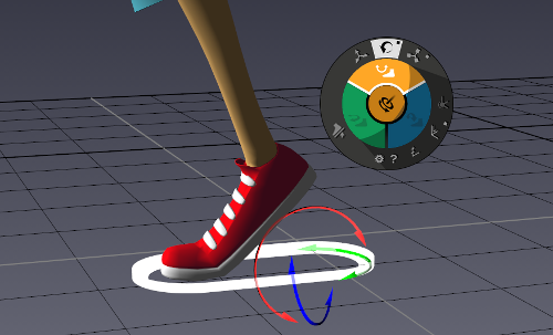
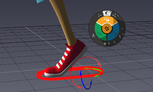
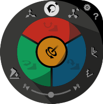
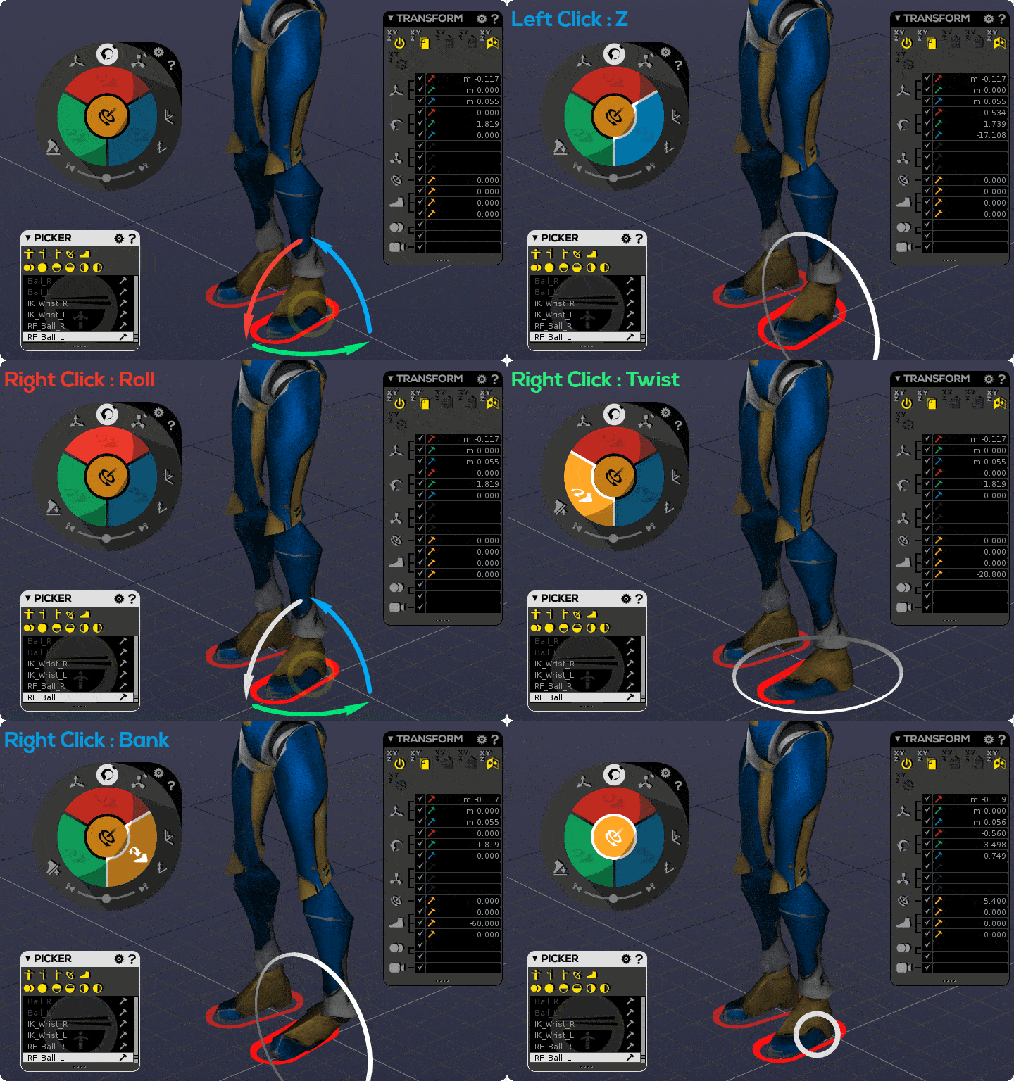
When a Reverse Foot sole is selected, the Spinner rotate part displays three new icons on Move, Rotate and Scale areas. Those areas can be used in two different ways:
- Using LMB on XYZ areas drives the rotation of the foot (sole)
- Using RMB on X area drives the Roll of the foot
- Using RMB on Y area drives the Twist of the foot
- Using RMB on Z area drives the Bank of the foot
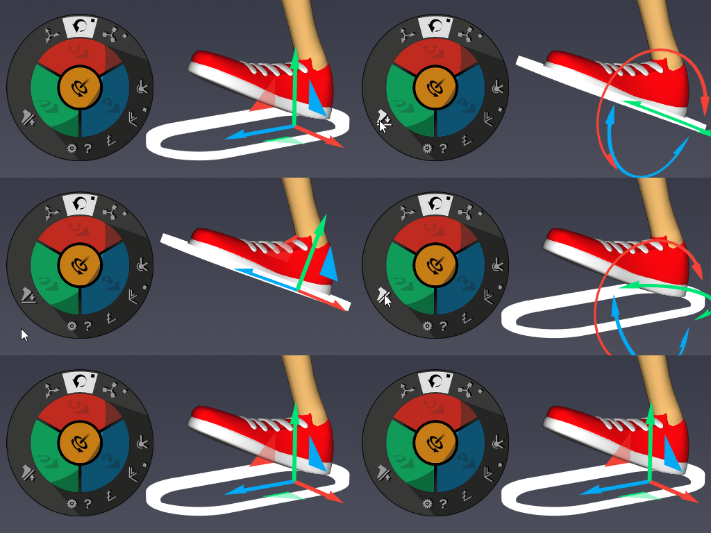
- Snap or Align: Snap your RF controller to foot sole or align it horizontally while preserving your pose (available in Spinner RF mode)
By the way, in similarity with IK target case, the central circular area handles the leg Pole Vector (or Pole Angle).
Snap or Align in action:
IK & Reverse Foot tangent mode
IK and Reverse Foot have their own tangent mode () in the Curveboard. It is the default mode for any target's curves but of course, you can manually tweak your tangents.
In this mode, the curve interpolation between two neighboring keys automatically switches between Spline, SplineClamped and Linear depending on the IK/FK combination, and the key values set on those keys.
Spline is the default mode. Other modes are activated in the following cases :
- When two successive keyframes are in different IK/FK mode (one is red and the other is white), the red key is deemed a contact point and all curves behave as in Linear mode.
- When two successive keyframes are in IK mode (both red), and key values on a curve are identical (or very close), akeytsu assumes this value mustn't vary between the keys, therefore this curve behaves as in Linear mode.
White target angles interpolation
The specific angles (pole, roll, twist and bank angles) of an IK target or a Reverse Foot target, in FK mode, have no impact during an interpolation between two animation keys. Even though their curve is shown, there is no string resolution: the joints positions are simply interpolated. A fortiori, their tangent modes have no impact either when interpolating with a key showing a white target.
IK & Reverse Foot in Transform, Cyclemaker, and Mixer features
All the features exposed in these windows operate on an IK controller, a reverse foot controller, or any joint of the associated string with the constraint of handling the whole joint string alongside with the controller. As a result, except for the Copy, Paste and Paste After actions, all operate on the string joints as a whole, and place the controller accordingly:
Hitting Reset on the controller or any of the string joint will reset the whole string to its bind pose positions, relatively to the string root parent.
Hitting Mirror or Cycle Side on the controller or any of the string joint will mirror the whole string.
Hitting Extract Stacker on the controller or any of the string joint will extract the whole string and the controller.
Hitting Merge Stackers will compute the string joints positions and adapt the target on the result. In the case of a reverse foot, an estimation of the roll, twist and bank angles will occur.
The Copy, Paste and Paste After behavior is quite different:
When copying and pasting the controller target alone, its values as a world object are impacted, and the controller is moved as a world object (allowing you to anchor the controller to the exact same spot in different animation keys for example).
When copying and pasting any of the string joints, the whole string is copied and pasted, relatively to the string root parent (allowing you to keep a limb still relatively to the rest of the body for example).
Copying and Pasting different strings
Due to non-identity of their chains in bind pose, copying and pasting from a string to another (for example from a left leg to a right leg) may not result in what you expect. In this case, you probably want to use the mirroring or cycling options.
It is of course possible to copy and paste from a controller target to another one.
Transform Actions and Channels
The actions operating on the strings are not meant to handle channel checkbox selections: anything but the “all checkboxes enabled” option may lead to random and unstable results.
Using Global Positions
Hierarchically speaking (in the tree window) the Reverse Foot Controller is not linked to the leg (like an IK controller, by the way). It is a direct child of the character. This choice allows you to use the transform window as global information:
- You can set a reverse foot orientation back to the horizontal by setting the X and Z rotation angles to 0.
- You can set a reverse foot position back to the ground by setting the Y translation value to 0.
How to use these skeleton templates?
Camera
This button allows you to create a new camera from the actual perspective viewpoint.
Once created, a camera will allow you to frame your scene through time, as such : you can key this object transforms/properties :
- Move X, Y, and Z
- Rotate X, Y, and Z
- FOV, which acts on the "Field of view". A high value (i.e : 109.00) will distort perspective, while a low value (i.e : 15.00) will flatten the view
To keyframe your camera, as for joints, IKs, ReverseFoots, Blendshapes, and since your camera object will be a new object : you'll need to tell akeytsu you want to keyframe it by adding "hammers" next to it in the picker. To know how to use hammers, please refer to the animation part and look for the Mixer and the Picker windows
Each new camera will be placed in the current character
You can decide to create a character node before creating a camera, so the camera will be stored in a dedicated character
If no character is selected, then akeytsu will generate a dedicated character for the camera
As other Akeytsu rig node, animated cameras must belong to a character. It implies too that those nodes use the common Build Pose/Ref Pose/Check Mode. Meaning that you create (and position) your camera in Build Pose. By default, the Build Pose will act as Ref Pose. So when you'll reset your transformations on animation keyframes, you will return to the init MRS of the Build Pose/Ref Pose. As always, if you need a different init posing, you can modify your camera position/orientation in Build Pose or create a custom Ref Pose.
By Default a camera is placed at the center of the scene in (0;0;0)
Access to default and animated cameras through the current view label using RMB (bottom left of current view) as shown in the following GIF :
Default cameras - List of default viewpoints (Perspective, top, bottom...etc)
Animated cameras - List of all your animated/custom cameras. Once selected, you can jump to your animated camera view using the shortcut "Shift+V"
Perspective: Displays perspective view (Shortcut "1" - top number key)
Front: Displays front orthographic view (Shortcut "2" - top number key)
Back: Displays back orthographic view (Shorcut "3" - top number key)
Right: Displays right orthographic view (Shorcut "4" - top number key)
Left: Displays left orthographic view (Shorcut "5" - top number key)
Top: Displays top orthographic view (Shorcut "6" - top number key)
Bottom: Displays bottom orthographic view (Shorcut "7" - top number key)
Camera Controls
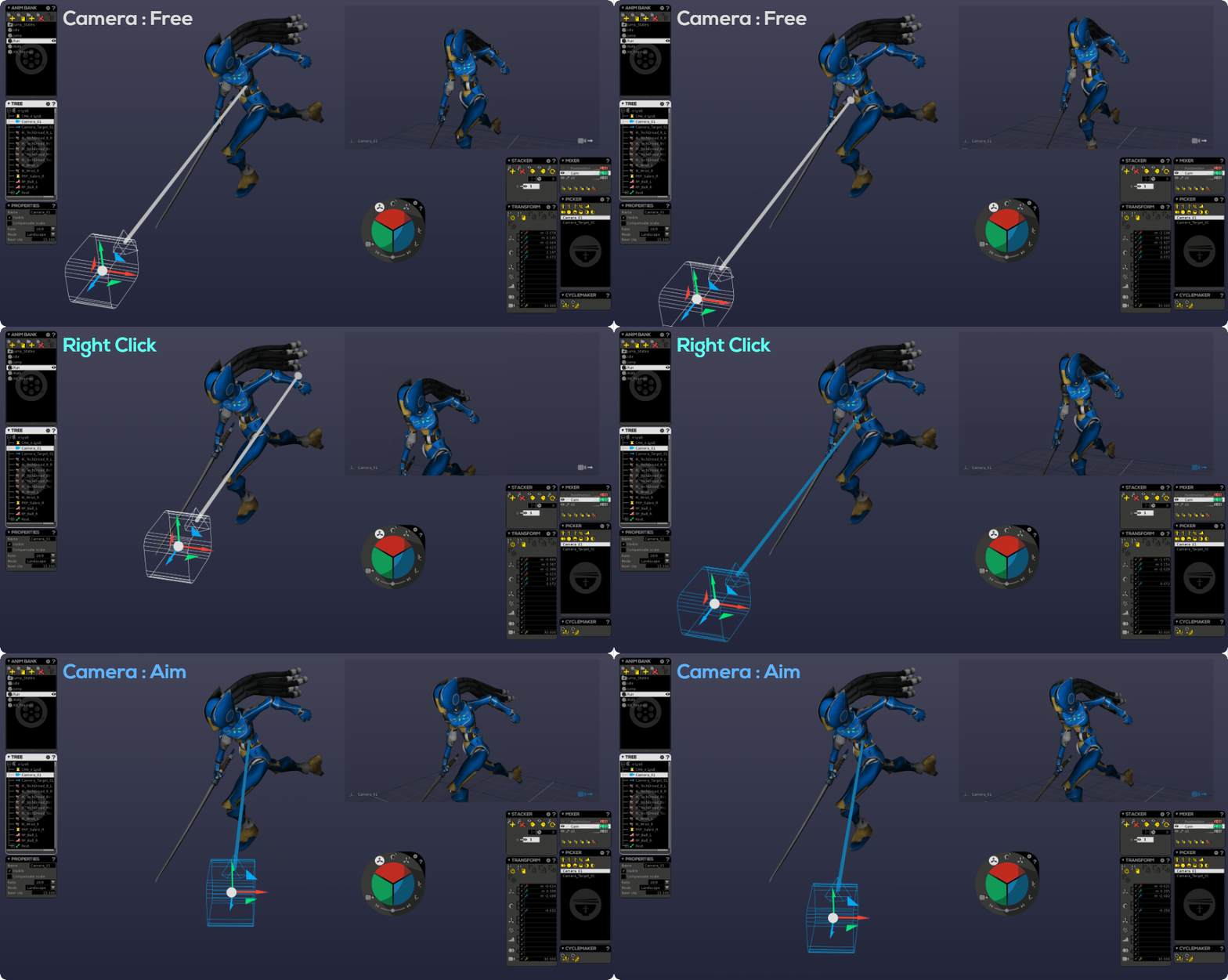
As shown below, you can switch between a free camera and a target camera. To do such, simply right click to any of its components (camera, target line/point)
- When the camera is white, you are in free mode
- When the camera is blue, you are in target mode
- When In Free mode, you can move and rotate the camera : the target will follow and target's interpolations inherits from camera's ones (as for a white IK)
- When In Target mode, moving the camera won't change the target position and the target will stay planted (as with a red IK)
- In both modes, the target always constrains the camera forward look axis. The camera looks at her target
To change the current view camera and go to your desired animated camera :
- Choose a viewport by clicking inside of it (like shown above, you can have a two view mode (shortcut : F2))
- Open the View & Preferences menu by clicking on this button at the left bottom corner :
- Hover your mouse pointer over the Animated cameras entry
- Pick the desired camera
The Properties window will display more settings about the selected animated camera :
- Ratio : choose the framing ration amonst a variety of available formats
- Mode : choose between Landscape & Portrait modes
- Near clip : define the plane where camera should start capturing elements
- Far clip : define the plane where camera should stop capturing elements
Rewind Camera Target: Recall the target position without affecting camera orientation
This smart feature, available into the Spinner while a camera is selected, allows you to quickly recall your target in its "init" position. Usefull to start a free camera (white) keyframe sequence after a target camera (blue) one!
Joint Orient Menu
This menu gives you options to orient your joints (pivots) according to "aim" and "2nd" settings.
Orient Joint: Orient selected joints according to the settings below.
- Aim settings: Choose what axis (x, y, z, -x, -y, -z) will always aim to the child joint, used as roll/twist axis.
- 2nd settings: Choose what axis (x, y, z, -x, -y, -z) will complete the father-joint-child plane, when associated with aim. You ought to experiment with this to find your preferred setting.
What about multi-child case?
Rig Atelier Preferences
Auto-orient on creation: Automatically orient your joints at creation, according to "aim" and "2nd" settings above.
Joint Snap YZ plane pixel threshold (ortho views): Allow to adjust the precision of Y or Z plane snap feature. Entering "0" will turn off this feature.
IK target scene size: Allows to resize the IK and Reverse Foot targets/soles of the current scene.
RF bank angle max value: Maximum angle values allowed concerning foot bank (scene setting).
RF twist angle max value: Maximum angle values allowed concerning foot twist (scene setting).
RF roll backward angle max value: Maximum angle value concerning foot roll on the heel (scene setting).
RF roll angle bending limit value: Maximum angle value concerning foot roll on the ball, without taking off the ball (scene setting).
RF roll angle unbending limit value: Angle value concerning foot roll on the ball, from ball take off up to straight foot (scene setting).
RF roll forward angle max value: Maximum angle value concerning foot roll on the toe (scene setting).
RF zero value snap threshold (Roll, Bank, Twist): Angle under which the foot snaps to 0 value (scene setting).

